|
Just like any other North American car made after
1996, the Diablo has an On Board Diagnostic or "OBDII socket" for a OBDII scan
tool. Government mandated rules specify that after the check engine
warning light comes on due to a fault, the engine control unit must record a
specific error code. The purpose of this code is to give precise information to
the service technician concerning the fault to allow its repair.
|
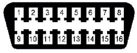
Fig 1 OBDII Socket Pins |
-
Pin 2 - J1850 Bus+
Pin 4 - Chassis Ground
Pin 5 - Signal Ground
Pin 6 - CAN High (J-2284)
Pin 7 - ISO 9141-2 K Line
Pin 10 - J1850 Bus
- Pin 11 Airbag Controller
- Pin 12 ABS Controller
- Pin 14 - CAN Low (J-2284)
Pin 15 - ISO 9141-2 L Line
Pin 16 - Battery Power
|
While the parameters, or readings,
required by OBDII regulations are uniform, the auto manufacturers
had some latitude in the communications protocol they used to
transmit those readings to scanners. Naturally, each felt they had
the one true way, so we have three different OBDII communications
protocols in use.
- As a
rule of thumb, GM cars and light trucks use SAE J1850 VPW (Variable
Pulse Width Modulation).
- Chrysler products and all European and most
Asian imports use ISO 9141 circuitry.
- Fords use SAE J1850 PWM (Pulse
Width Modulation) communication patterns.
|
|
Unlike the Diablo, the Gallardo does not put out OBDII codes that are
compatible with older diagnostic readers.
The Gallardo issues information at the OBDII socket on the
CAN lines (Pins 6 & 14). For this reason if you wish to read error
information you must have one of the newer OBDII readers that understands the
CAN data lines. Most past recent cars are switching to this format and the
newer OBDII readers are being modified to understand it. I have not looked
into this area extensively yet. Currently I am using the "ElmScan
5 Scan Tool". There are a number of
software packages
that work with this unit. I like "PCMSCAN".
I had a bad experience with one called PRScan (no technical support). The
ElmScan interface connects to a laptop, so you can expect the software to evolve
over time. With the above setup you can get an enormous amount of real
time information about your engine. According to the Lamborghini Gallardo
technical manual the following engine codes are put out:-
|
|
Component/System
|
Fault code
|
Monitor Strategy
Description |
Primary malfunction
detection parameter |
Fault Activation range
|
Time length of the
fault |
Frequency of check
|
- CATALYST
SYSTEM EFF.
- Bank 1
|
P0420 |
Functional check
|
front/rear oxygen ratio
|
< 4 |
5 faults in 10 times
|
Once per driving cycle
|
- CATALYST SYSTEM
EFF.
- Bank 2
|
P0430 |
Functional check
|
front/rear oxygen ratio
|
< 4 |
5 faults in 10 times
|
Once per driving cycle
|
|
RANDOM MISFIRE
|
P0300 |
|
Random Misfire
detection |
|
|
|
-
RANDOM MISFIRE
- Bank1
|
P1305 |
Misfire detection with
exhaust Pressure sensor |
Misfire Index AND
Harmonics Amplitude of Exhaust pressure signal |
MI>Threshold AND HA Off
Range function of RPM and MAP |
1s |
Continuous |
|
RANDOM MISFIRE
Bank2 |
P1306 |
Misfire detection with
exhaust Pressure sensor |
Misfire Index AND
Harmonics Amplitude of Exhaust pressure signal |
MI>Threshold AND HA Off
Range function of RPM and MAP |
1s |
Continuous |
|
CYLINDER 1 MISFIRE
DETECTED |
P0301 |
Misfire detection with
exhaust Pressure sensor |
Misfire Index,
Harmonics Amplitude AND Phase of Exhaust pressure signal
|
MI>Threshold HA in
Range AND Phase in Range function of RPM and MAP |
1s |
Continuous |
|
CYLINDER 2 MISFIRE
DETECTED |
P0302 |
Misfire detection with
exhaust pressure sensor |
|
Same as P0301
|
|
|
|
CYLINDER 3 MISFIRE
DETECTED |
P0303 |
Misfire detection with
exhaust pressure sensor |
|
Same as P0301
|
|
|
|
CYLINDER 4 MISFIRE
DETECTED |
P0304 |
Misfire detection with
exhaust pressure sensor |
|
Same as P0301
|
|
|
|
CYLINDER 5 MISFIRE
DETECTED |
P0305 |
Misfire detection with
exhaust pressure sensor |
|
Same as P0301
|
|
|
|
CYLINDER 6 MISFIRE
DETECTED |
P0306 |
Misfire detection with
exhaust pressure sensor |
|
Same as P0301
|
|
|
|
CYLINDER 7 MISFIRE
DETECTED |
P0307 |
Misfire detection with
exhaust pressure sensor |
|
Same as P0301
|
|
|
|
CYLINDER 8 MISFIRE
DETECTED
|
P0308 |
Misfire detection with
exhaust pressure sensor |
|
Same as P0301
|
|
|
|
CYLINDER 9 MISFIRE
DETECTED
|
P0309 |
Misfire detection with
exhaust pressure sensor |
|
Same as P0301
|
|
|
|
CYLINDER 10 MISFIRE
DETECTED
|
P0310 |
Misfire detection with
exhaust pressure sensor |
|
Same as P0301
|
|
|
|
|
Component/System |
Fault code |
Monitor Strategy
Description
|
Primary malfunction
detection parameter
|
Fault Activation range |
Time length of the
fault
|
Frequency of check |
-
EXHAUST PRESSURE SENSOR
- BANK 1
|
P1311 |
Functional check |
Exhaust sensor pressure
signal
|
MI < Threshold |
10 s |
Continuous |
|
P1312 |
Low input |
Exhaust sensor pressure
signal
|
< 0.5 V |
10 s |
Continuous |
|
P1313 |
High input |
Exhaust sensor pressure
signal
|
> 4.9 V |
10 s |
Continuous |
-
EXHAUST PRESSURE SENSOR
- Bank 2
|
P1314 |
Functional check |
Exhaust sensor pressure
signal
|
MI < Threshold |
10 s |
Continuous |
|
P1315 |
Low input |
Exhaust sensor pressure
signal
|
< 0.5 V |
10 s |
Continuous |
|
P1316 |
High input |
Exhaust sensor pressure
signal
|
> 4.9 V |
10 s |
Continuous |
|
|
Component/System |
Fault code |
Monitor Strategy Description
|
Primary malfunction detection parameter
|
Fault Activation range |
Time length of the fault |
Frequency of check |
-
OXYGEN SENSOR FRONT
- Bank 1
|
P0133 |
Response Rate |
Switching frequency AND Quick output change
counter
|
S_FREQ < 15 or QOCC < 60
|
|
Once per driving cycle
|
|
P0134 |
Oxygen sensor inactive |
Oxygen sensor output voltage
|
0.4 < V < 0.55 |
60 s |
Continuous |
|
P2195 |
Oxygen sensor stuck lean |
Oxygen sensor output voltage
|
0.01 ≤ V < 0.4 |
30 s |
Continuous |
|
P2196 |
Oxygen sensor stuck rich |
Oxygen sensor output voltage
|
0.55 < V < 1.05 |
60 s |
Continuous |
|
P0131 |
Oxygen sensor locked lean |
Oxygen sensor output voltage
|
< 0.01 V |
30 s |
Continuous |
|
P0132 |
Oxygen sensor locked rich |
Oxygen sensor output voltage
|
≥ 1.05 V |
60 s |
Continuous |
-
OXYGEN SENSOR REAR
- Bank 1
|
P0140 |
Oxygen sensor inactive |
Oxygen sensor output voltage
|
0.4 < V < 0.55 |
60 s |
Continuous |
| |
Transient test |
Oxygen sensor output voltage
|
V> 0.5 |
10 times |
Continuous |
| |
|
|
V< 0.5 |
10 times |
Continuous |
|
P2270 |
Oxygen sensor stuck lean |
Oxygen sensor output voltag
|
0.01 ≤ V < 0.1 |
300 s |
Continuous |
|
P2271 |
Oxygen sensor stuck lean |
Oxygen sensor output voltag
|
0.07 < V < 1.05 |
300 s |
Continuous |
|
P0137 |
Oxygen sensor locked lean |
Oxygen sensor output voltage
|
< 0.01 V |
300 s |
Continuous |
|
P0138 |
Oxygen sensor locked rich |
Oxygen sensor output voltage
|
≥ 1.05 V |
300 s |
Continuous |
-
OXYGEN HEATER FRONT
- Bank 1
|
P0135 |
Functional check |
Oxygen sensor output voltage
|
0.4 < V < 0.55 |
5 s |
Once per driving cycle |
-
OXYGEN HEATER REAR
- Bank 1
|
P0141 |
Functional check |
Oxygen sensor output voltage
|
0.4 < V < 0.55 |
10 s |
Once per driving cycle |
|
|
Component/System |
Fault code |
Monitor Strategy Description
|
Primary malfunction detection parameter
|
Fault Activation range |
Time length of the fault |
Frequency of check |
-
OXYGEN SENSOR FRONT
- Bank 2
|
P0153 |
Response Rate |
Switching frequency AND Quick output
change counter |
Same as P0133 |
|
Once per driving cycle |
|
P0154 |
Oxygen sensor inactive |
Oxygen sensor output voltage
|
0.4 < V < 0.55 |
60 s |
Continuous |
|
P2197 |
Oxygen sensor locked lean |
Oxygen sensor output voltage
|
0.01 ≤ V < 0.4 |
30 s |
Continuous |
|
P2198 |
Oxygen sensor locked rich |
Oxygen sensor output voltage
|
0.55 < V < 1.05 |
60 s |
Continuous |
|
P0151 |
Oxygen sensor locked lean |
Oxygen sensor output voltage
|
< 0.01 V |
30 s |
Continuous |
|
P0152 |
Oxygen sensor locked rich |
Oxygen sensor output voltage
|
≥ 1.05 V |
60 s |
Continuous |
-
OXYGEN SENSOR REAR
- Bank 2
|
P0160 |
Oxygen sensor inactive |
Oxygen sensor output voltage
|
0.4 < V < 0.55 |
60 s |
Continuous |
|
|
Transient test |
Oxygen sensor output voltage
|
V> 0.5 |
10 times |
Continuous |
|
|
|
|
V< 0.5 |
10 times |
Continuous |
|
P2272 |
Oxygen sensor locked lean |
Oxygen sensor output voltage
|
0.01 ≤ V < 0.1 |
300 s |
Continuous |
|
P2273 |
Oxygen sensor locked rich |
Oxygen sensor output voltage
|
0.07 < V < 1.05 |
300 s |
Continuous |
|
P0157 |
Oxygen sensor locked lean |
Oxygen sensor output voltage
|
< 0.01 V |
300 s |
Continuous |
|
P0158 |
Oxygen sensor locked rich |
Oxygen sensor output voltage
|
≥ 1.05 V |
300 s |
Continuous |
|
OXYGEN HEATER FRONT Bank 2
|
P0155 |
Functional check |
Oxygen sensor output voltage
|
0.4 < V < 0.55 |
5 s |
Once per driving cycle |
|
OXYGEN HEATER REAR Bank 2
|
P0161 |
Functional check |
Oxygen sensor output voltage
|
0.4 < V < 0.55 |
10 s |
Once per driving cycle |
INTAKE CAMSHAFT POSITION SENSOR
Bank 1
|
P0341 |
Response |
Cam sensor signal |
Repetition of the same sector of the cam signal after one revolution of thecrankshaft
|
20 times |
Continuous |
|
|
|
|
|
|
|
|
|
|
|
|
|
|
|
|
|
|
|
|
|
|
|
Component/System |
Fault code |
Monitor Strategy Description
|
Primary malfunction detection parameter
|
Fault Activation range |
Time length of the fault |
Frequency of check |
EXHAUST CAMSHAFT POSITION SENSOR
Bank 1
|
P0366 |
Response |
Cam sensor signal |
Repetition of the same sector of the
cam signal after one revolution of the crankshaft |
20 times |
Continuous |
INTAKE CAMSHAFT POSITION SENSOR
Bank 2
|
P0346 |
Response |
Cam sensor signal |
Repetition of the same sector of the
cam signal after one revolution of the crankshaft |
20 times |
Continuous |
EXHAUST CAMSHAFT POSITION SENSOR
Bank 2
|
P0391 |
Response |
Cam sensor signal |
Repetition of the same sector of the
cam signal after one revolution of the |
20 times |
Continuous |
|
|
Component/System |
Fault code |
Monitor Strategy Description
|
Primary malfunction detection parameter
|
Fault Activation range |
Time length of the fault |
Frequency of check |
|
|
|
|
|
crankshaft |
|
|
|
CRANKSHAFT POSITION SENSOR
|
P0336 |
Response |
Crank sensor signal |
If the same tooth of the crankshaft
|
|
|
|
|
|
|
|
flywheel is recognized after two
consecutive |
|
|
|
|
|
|
|
edges of the cam signal |
20 times |
Continuous |
|
SIGNAL SEQUENCE |
P1310 |
Response |
Intermittent loss of signal (blip)
|
coherence between sectors |
|
|
|
|
|
|
|
of the cam signal and specific teeth of
the crankshaft |
|
|
|
|
|
|
|
flywheel |
20 times |
Continuous |
-
MANIFOLD ABSOLUTE PRESSURE /
- BAROMETRIC PRESSURE
|
P0105 |
Functional check |
Comparison between manifold absolute pressure and barometric pressure
|
> 30 mmHg |
|
At the key on |
|
|
|
|
|
|
|
|
|
|
|
|
|
|
|
|
|
P1106 |
Functional check |
Comparison between ECU bank1 value and
ECU bank2 value |
> 25mmHg |
4 s |
Continuous |
|
|
P1107 |
Low input |
Manifold absolute pressure sensor
signal |
< 105 mmHg |
16 s |
Continuous |
|
|
P1108 |
High input |
Manifold absolute pressure sensor
signal |
> 809 mmHg |
16 s |
Continuous |
|
|
P1109 |
Low input |
Barometric pressure sensor signal
|
< 105 mmHg |
16 s |
Continuous |
|
|
P1110 |
High input |
Barometric pressure sensor signal
|
> 809 mmHg |
16 s |
Continuous |
|
BATTERY VOLTAGE |
P1101 |
Low output |
Battery voltage |
< 10 V |
20 times |
Continuous |
|
P1102 |
High output |
Battery voltage |
> 15 V |
20 times |
Continuous |
|
|
Component/System |
Fault code |
Monitor Strategy Description
|
Primary malfunction detection parameter
|
Fault Activation range |
Time length of the fault |
Frequency of check |
|
ENGINE COOLANT TEMPERATURE |
P0116 |
Functional check |
Comparison between ECU LIE value and
CAN BUS value |
> 15 °C |
5 s |
Continuous |
|
|
P0117 |
Low Input |
Coolant temperature sensor |
< -20 °C |
250 s |
Continuous |
|
|
P0118 |
High input |
Coolant temperature sensor |
> 120 °C |
1 s |
Continuous |
|
IDENTIFICATION “LIE” ECU
|
P1601 |
Range check |
Pin detection |
No pin detected |
10 times |
At the key on |
|
INTAKE AIR TEMPERATURE |
P0111 |
Functional check |
Derivative Air temperature sensor
signal |
> 15 °C/0.5 sec |
5 sec |
Continuous |
|
|
P0112 |
Low input |
Air temperature sensor |
< -25° C |
1200 s |
Continuous |
|
|
P0113 |
High input |
Air temperature sensor |
> 120 °C |
1s |
Continuous |
|
DRIVE BY WIRE |
P0226 |
Functional check |
Data |
Component found failed |
|
Continuous |
|
|
P0227 |
Low input |
Throttle position signal |
< 0° |
5 s |
Continuous |
|
|
P0228 |
High input |
Throttle position signal |
> 81° |
5 s |
Continuous |
|
|
P1226 |
set in case of throttle malfunction
detected by ECU Bank 1 |
|
|
|
|
|
P1227 |
set in case of throttle malfunction
detected by ECU Bank 2 |
|
|
|
|
PEDAL POSITION |
P0121 |
Functional check |
Comparison between sensor “A” and
sensor “B” |
> 10% |
3 s |
Continuous |
|
P0122 |
Pedal position sensor “A” Low Input
|
Pedal position signal |
< Threshold |
5 s |
Continuous |
|
P0123 |
Pedal position sensor “A” High Input
|
Pedal position signal |
> Threshold |
5 s |
Continuous |
|
P0222 |
Pedal position sensor “B” Low Input
|
Pedal position signal |
< Threshold |
5 s |
Continuous |
|
P0223 |
Pedal position sensor “B” High Input
|
Pedal position signal |
> Threshold |
5 s |
Continuous |
|
|
Component/System |
Fault code |
Monitor Strategy Description
|
Primary malfunction detection parameter
|
Fault Activation range |
Time length of the fault |
Frequency of check |
|
EVAPORATIVE EMISSION CONTROL SYSTEM
|
P0441 |
Insufficient Purge Flow |
Evaporative System Pressure
|
<Threshold |
3 s |
Once per driving cycle |
|
|
P0442 |
Leak detected |
Evaporative System Pressure
|
<Threshold |
20 s |
same as P0441 |
|
|
P0443 |
Purge Control Valve Malfunction
|
Feedback-test |
Incorrect data feedback |
|
Once per driving cycle |
|
|
P0446 |
Vent Control Valve Malfunction
|
Feedback-test |
Incorrect data feedback |
|
Once per driving cycle |
|
|
P0450 |
Pressure Sensor Malfunction
|
Evaporative System Pressure
|
< -1 mbar or > 1 mbar |
|
at Key-on |
|
|
|
|
Evaporative System Pressure
|
>4.9 V |
|
continuos |
|
|
|
|
Evaporative System Pressure
|
< 0.5 V |
|
continuos |
|
|
|
|
Evaporative System Pressure
|
< -15 mbar or > |
3 s |
Once per driving |
|
|
|
|
|
5 mbar |
|
cycle |
|
IDLE CONTROL SYSTEM |
P0506 |
Functional check |
RPM RPMf(TH2O) |
RPM < |
10 s |
Once per driving cycle |
|
|
|
|
|
< 840 rpm |
5 s |
Once per driving cycle |
|
|
P0507 |
Functional check |
RPM |
RPM > RPMf(TH2O) |
10 s |
Once per driving cycle |
|
|
|
|
|
> 1080 rpm |
5 s |
Once per driving cycle |
|
SERIAL COMMUNICATION |
P0600 |
ISO 9141 Line failure |
Data communications |
Incorrect data feedback |
|
Once per driving cycle |
|
INTERNAL CONTROL MODULE
|
P0605 |
Internal routine |
Data |
Component found failed |
|
Once per driving cycle |
|
|
Component/System |
Fault code |
Monitor Strategy Description
|
Primary malfunction detection parameter
|
Fault Activation range |
Time length of the fault |
Frequency of check |
|
FUEL SYSTEM Bank 1 |
P0171 |
Fuel trim system too lean |
Fuel trim correction |
> +0.75 ms |
30 s |
Continuous |
|
|
P0172 |
Fuel trim system too rich |
Fuel trim correction |
< -0.75 ms |
30 s |
Continuous |
|
FUEL SYSTEM Bank 2 |
P0174 |
Fuel trim system too lean |
Fuel trim correction |
> +0.75 ms |
30 s |
Continuous |
|
P0175 |
Fuel trim system too rich |
Fuel trim correction |
< -0.75 ms |
30 s |
Continuous |
|
|
Component/System |
Fault code |
Monitor Strategy Description
|
Primary malfunction detection parameter
|
Fault Activation range |
Time length of the fault |
Frequency of check |
-
CATALYST TEMPERATURE
- Bank 1
|
P1401 |
Catalyst overtemp.
1st level |
Catalyst temp sensor signal
|
> 900 °C < 940 °C |
1 s |
Continuous |
|
|
P1402 |
Catalyst overtemp.
2nd level |
Catalyst temp sensor signal
|
> 940 °C |
1 s |
Continuous |
|
|
P0427 |
Low input |
Catalyst temp sensor signal
|
< 20°C |
60 s |
Continuous |
|
|
P0428 |
High input |
Catalyst temp sensor signal
|
970°C |
|
At The Key on |
-
CATALYST TEMPERATURE
- Bank 2
|
P1405 |
Catalyst overtemp.
1st level |
Catalyst temp sensor signal
|
> 900 °C < 940 °C |
1 s |
Continuous |
|
|
P1406 |
Catalyst overtemp.
2nd level |
Catalyst temp sensor signal
|
> 940 °C |
1 s |
Continuous |
|
|
P0437 |
Low input |
Catalyst temp sensor signal
|
< 20°C |
60 s |
Continuous |
|
|
P0438 |
High input |
Catalyst temp sensor signal
|
970°C |
|
At The Key on |
|
CATALYST TEMPERATURE |
P1426 |
Functional check |
|Catalyst temp sensor signal
|
> 200°C |
60 s |
Continuous |
|
|
|
|
Bank1 - Catalyst temp sensor
|
|
|
|
|
|
|
|
signal Bank2| |
|
|
|
|
CAN COMMUNICATION |
P1602 |
Data failure |
Data communications |
Incorrect data feedback |
3 s |
Continuous |
|
THERMOSTAT |
P0128 |
Functional check |
Engine Coolant Temperature |
< 70 °C |
5 s |
Once per driving cycle |
|
SECONDARY AIR INJECTION Bank1
|
P0491 |
Functional check |
Oxygen sensor output voltage
|
V > 0.3 [V] |
2s |
Once per driving cycle |
|
SECONDARY AIR INJECTION Bank2
|
P0492 |
Functional check |
Oxygen sensor output voltage
|
V > 0.3 [V] |
2s |
Once per driving cycle |
|
SECONDARY AIR INJECTION
|
P0412 |
Electro Valve feedback-test |
Feedback-test |
Incorrect data |
|
Once per driving |
|
ELECTRO VALVE |
|
|
|
feedback |
|
cycle |
|
|
Component/System |
Fault code |
Monitor Strategy Description
|
Primary malfunction detection parameter
|
Fault Activation range |
Time length of the fault |
Frequency of check |
|
OIL TEMPERATURE
|
P0197 |
Low input |
Oil temperature signal output
|
< 20 bit |
2s |
Continuous |
|
|
P0198 |
High input |
Oil temperature signal output
|
> 1000 bit |
2s |
Continuous |
|
INTAKE VARIABLE VALVE TIMING CONTROL
Bank1 |
P1366 |
Functional check |
VVT position Target - VVT position
|
10 deg |
2s |
Continuous |
|
EXHAUST VARIABLE VALVE TIMING CONTROL
Bank1 |
P1367 |
Functional check |
VVT position Target - VVT position
|
10 deg |
2s |
Continuous |
|
INTAKE VARIABLE VALVE TIMING CONTROL
Bank2 |
P1368 |
Functional check |
VVT position Target - VVT position
|
10 deg |
2s |
Continuous |
|
EXHAUST VARIABLE VALVE TIMING CONTROL
Bank2 |
P1369 |
Functional check |
VVT position Target - VVT position
|
10 deg |
2s |
Continuous
|
|