 |

|
|
|
|
||
|
Rick Schue has
submitted the following write-up in our
forum section. I have copied it here so more people will
see it. He has dome a fantastic job of describing how to change the
brake pads in a Gallardo. Thanks Rick! |
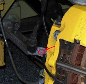
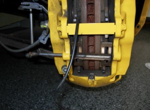
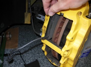
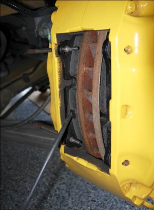
 Figure 1. Front Gallardo (Brambo) Brake |
|
|
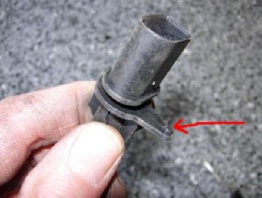
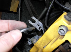
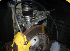
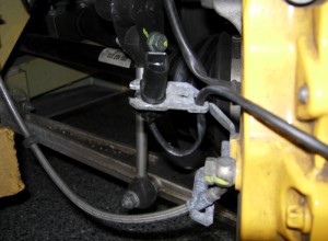
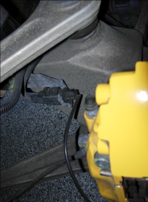
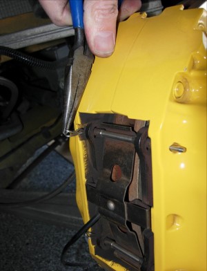
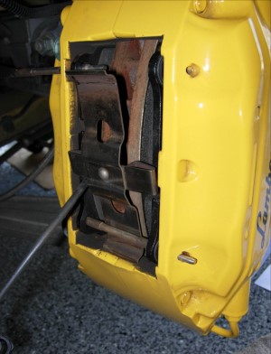
Believe it or nor replacing the rear pads is more difficult than the front. So we will start with the Front Pads. Front Brake Pads Jack up one side of the front and remove the road wheel. Turn the steering wheel to position the wheel to make access to the caliper easier. Locate the connector for the brake wear sensor and notice the keying hole in the bracket (red arrow in Fig 2). This mates with a tab on the brake pad sensor (fig 3). |
||
 |
 |
 |
| Figure 2. | Figure 3. | Figure 4. |
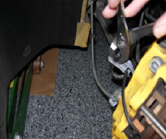
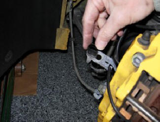
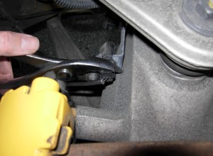
To remove the connector from the bracket, you need to rotate it 90 degrees, then slide it out of the bracket. I found it easier to unplug the connector from the wiring harness after it was free of the bracket (after these photos were taken). Use a pair of large pliers and grasp the connector and rotate. The keying "pin" will offer some resistance, then it will slip out of the keying hole and the connector will rotate. Then slide it out of the bracket.
 |
 |
 |
| Figure 5. | Figure 6. | Figure 7. |
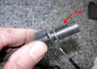
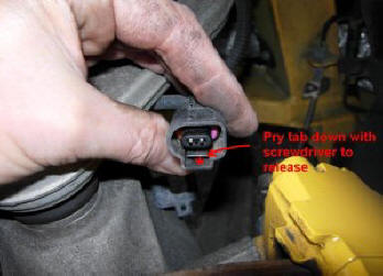
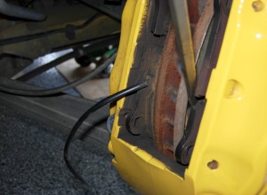
The mating plug is held in place by a barb on the pad wire connector. To release the plug, insert a small screw driver into plug and pry the tab away from the barb, then pull (see fig 6). These photos were taken after the connectors were separated to show you what and where to pry. Free the pad wire from the bracket (fig 8).
Now the hard stuff is done.
From here on, it's easy!
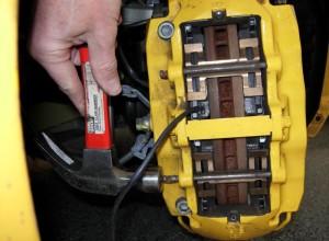
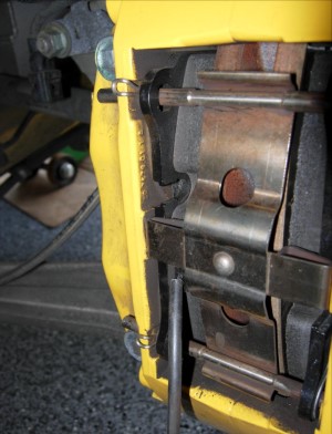
Gently tap the two retaining pins
out with a hammer. It doesn't take much force. Be careful to not
damage the paint. I started with a large punch, then switched to a
small one that would fit through the hole (fig 9). Then pull the
pins out by hand and remove the spring clips (fig 10).
 |
 |
 |
| Figure 8. | Figure 9. | Figure 10. |
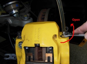
Remove the rubber cap from the outboard bleed nipple and insert one end of the plastic tubing. Loop the tubing up into the suspension and insert the far end into a suitable container (fig 11). The loop in the tube will make sure that the bleed nipple is always covered by brake fluid and no air enters the system. With an 11mm open end wrench, loosen the nipple about 1/4 turn (fig 12). You may need to reposition the tubing on the nipple to keep the nipple open (otherwise the torque on the tubing may tend to rotate the nipple closed).
 |
 |
|
| Figure 11. | Figure 12. |
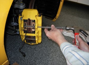
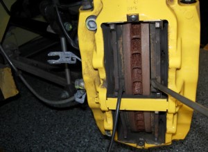
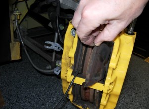
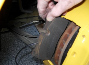
Now pry the old pads away
from the rotor. They will push the pistons back into the calipers,
causing brake fluid to flow out into the tube. The pads should move
easily, if they don't, make sure the bleed nipple is still open.
Start prying against one of the notches in the pad, then once
you have some space between the pad and rotor, pry from various
points to keep the pad parallel to the rotor until it is fully
retracted (fig 13). After all the pads have been retracted
into the caliper, gently pull them out. They should come out easily.
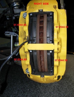
On the back of each pad is a part number. Each side has three
different part numbers. Make a note of which goes where (fig 14).
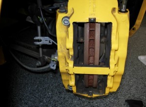
After all pads are out, visually check the inside of the caliper to
make sure all pistons are fully retracted (fig 15).
 |
 |
 |
| Figure 13. | Figure 14. | Figure 15. |
Close the bleed nipple. DO NOT
over-tighten. Carefully remove the bleed tube, making sure not to drip
brake fluid on the caliper. Replace the rubber cap on the nipple and clean
up any spilled brake fluid. Brake fluid damages paint, so be sure to clean
up the area well.
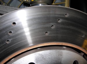
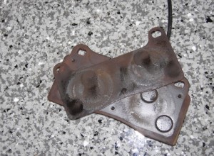
This is a good time to check the rotors for any
cracks or fractures around the holes. If you see anything suspicious,
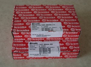
replace the rotors! This rotor appears to be OK (fig 15). The new
pads are specific to each side of the rotor - with 4 different part
numbers for the front and 2 part numbers for the rear (fig 16).
 |
 |
 |
| Figure 15. | Figure 16. | Figure 16. |
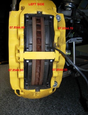
Install the correct pad at each location. Figure 17 is for the RIGHT FRONT: Figure 18 is for the LEFT FRONT:
 |
 |
|
| Figure 17. | Figure 18. |
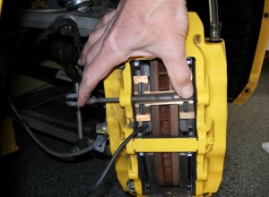
Now reinstall the springs and retaining pins removed earlier. Press down on the springs to allow the pins to mate with the far hole in the caliper (fig 19). Once the pins are positioned properly, gently tap them in with a hammer until they are fully seated. As you tap them in, you will hear change in the sound the pin makes when it becomes fully seated in the caliper (fig 20).
 |
 |
|
| Figure 19. | Figure 20. |
Reinstall the wear sensor
connector into the bracket. Slide it in and then rotate 90 degrees
until the tab snaps into the keying hole.
NOTE: You may want to
press down on the tab so it clears the bracket as you rotate it into
place. You don't want to shear off the keying pin or break off the
tab!
Loop the wire to the pad into the
hook on the bracket. Adjust the slack in the wire to the pad so that it does not
touch the caliper (heat issues?). Connect the wire harness plug (see fig 21).
 |
||
| Figure 21. |
This completes one side of the front. Push down on the brake pedal to seat the pads against the rotor. Check for any brake fluid leaks at the bleed nipple.
Before reinstalling the road wheel, make the following double-checks:-
a. Wear sensor plug connected.
b. Sensor wire secured into bracket hook, not touching
caliper.
c. Bleed nipple closed
and capped.
Repeat this procedure on the other side.
|
Rear
Brake Pads Jack up the rear of the car and remove the road wheels. Locate the wear sensor connector bracket (fig 22). As done on the front, grasp the connector with a pair of pliers and rotate 90 degrees, then slide it out of the bracket (fig 23). Then unplug the connector from the wiring harness. The retaining pins on the rear brakes are held in place with cotter pins. Remove both cotter pins with a needle nosed pliers. Use care not to mar the paint (fig 24). Then remove one of the pins by tapping it out with a punch as for the front pads. Attach the bleed tube to the outboard bleed nipple and as before for the front brakes open the bleed nipple. |
 |
 |
 |
| Figure 22. | Figure 23. | Figure 24. |
Pry the pads away from the rotor, using the notch in the pads. Then insert the screwdriver against the pads and rotor at various places to keep them parallel as the pistons retract into the caliper (fig 25). Remove the pads. There are only two kinds of pads on the rear - those with wear sensors (wires) and those without, so you shouldn't need to keep track of which went where (fig 26).
Note:
The rear pads have thin metal shims on
the back (fig 27). These may become separated from the pads. Make sure these are
removed from the caliper! Close off the bleed nipple, remove the bleed
hose. Cap the nipple and clean up any spilled brake fluid.
Insert the new
pads. The pads with the wires go on the inside.
 |
 |
 |
| Figure 25. | Figure 26. | Figure 27. |
The holes through the pad
backplates match up with the pins, so don't push the pads all the way down
into the caliper (like was done on the front). Use a small diameter punch
to align the pad holes with caliper, otherwise reinserting the pins will
be very frustrating. Replace the spring clip and insert the bottom
pin into the caliper. Note the location of the cotter pin hole and rotate
the pin so that the cotter pin can be inserted after the pin is fully
installed.
Then press down on the free end of the spring clip to allow the second pin to be inserted into the caliper. This is the difficult part. You may need to use a tool (large screwdriver) to press down on the clip as you insert the last pin. Be sure to rotate the pin so that the cotter pin hole is in the correct position. Double check the alignment of the pad with the far hole with a punch if you have trouble getting the pin to mate with the outboard hole (see figure 29 below).
Once the pins are in, insert the cotter pins. (You DID make sure the pins were
rotated correctly?)
Check to make sure the springs are positioned so that
they mate up with the "thin" portion of the pins. The photo below (fig 30),
shows the spring in the proper position with the bottom pin, while the spring is
slightly out of position on the top.
 |
 |
 |
| Figure 28. | Figure 29. | Figure 30. |
Reinstall the wear sensor
connector into bracket. Rotate it 90 degrees by grasping the back of
the connector with pliers.
NOTE: You may want to press down on
the tab so it clears the bracket as you rotate it into place. You
don't want to shear off the keying pin or break off the tab!
Then reconnect the plug from the wiring harness.
That's it for this side.
Before moving on to the other, perform the following double-checks:-
a. Wear sensor wire connected.
b. Cotter pins installed.
c. Bleed nipple
closed and all brake fluid cleaned up.
Before driving
the car, push down on the brake pedal several times until the pedal
firms up. This pushes the pads back against the rotors. Then check
the brake fluid level and replace fluid as needed. You should need
to replace roughly the same amount of fluid you collected in the
waste jar. After the pads are bedded-in, check the fluid again to
confirm that there are no leaks.
Bedding In The New Pads
It is
important that the new pads be "bedded in" after they are installed.
This consists of a series of stops from various speeds to heat the
pads as they conform to the rotor surface. If you are installing new
pads on "old" (un-resurfaced) rotors, the new pads initially will
only touch the rotors on the "high" spots. This can cause localized
heating on the pads, resulting in glazing if not bedded in properly.
Refer to the pad manufacturer's web site for bedding-in procedures.