 |

|
|
|
|
||
Installing a Battery Disconnect Switch in a Gallardo
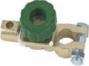
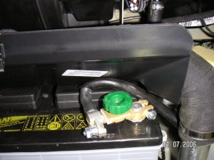
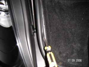
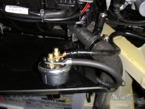
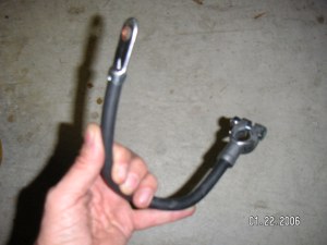
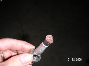
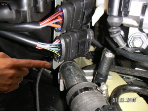
Be sure to attach the switch to the negative battery terminal. You will have to loosen the attachment hook the binds the large negative lead wide to the frame at one place to get more of a length on the wire loser to the battery. The angle of the switch is not great but it has to be like this so the trunk door flap will close. The only complication in putting in the trunk box is reattaching the rubber waterproof seal. Having tried a number of way with some frustration let me say the best way is to install the rubber seal first on the car, attaching it all the way around the trunk box plastic frame/holder. Press it down real well. Then insert the trunk box. Now the hard part, with a screwdriver tease the rubber lip of the seal over the top edge of the trunk box. Work all the way around (see fig. 7). This is not as easy as it looks! Finally when tightening down the switch to close the circuit always remember to make sure it is tight to avoid a bad battery connection. This is a simple install and well worth the time and effort. One point I should mention, for a switch like this it is essential that the green knob of switch be screwed down real tight to close the circuit. If it is loose it will shake open disconnecting the battery leading to possible engine stopping, alternators failure etc. I now have replaced the above switch with a second more robust switch. It is one of many found in most well equipped auto stores. It is completely self enclosed and has an on/off knob. If you work on your car a lot and want a more reliable switch then you should use a switch like this (see below). In order to connect a large switch like this you need a place to put it that is easily accessible. I attached it to the plastic "cover" over the battery as shown in figure 7. The one complication we have is: the ground lead is too short. A second short lead (fig 8) is needed. This is attached to the battery and one pole of the switch. Disconnect the + wire for the battery while you are doing this. Also make sure all connections are tight. Then you need to cut the battery connector on the ground lead (using a hacksaw) and attach a copper nut attachment post (see fig 9, 10). This needs to be well soldered to the copper lead. I use a propane/oxygen burner to heat the copper lead and melt the solder. It is very important that a good connection is made. Make sure the joint is well soldered. Again attach and tighten this lead to the other switch pole (see fig 7). Finally one other small improvement. There is a bracket above the switch that gets in the way of the switch (fig 11, 12 & 13). It holds two wire connectors but sticks down in the way of the switch. Remove the bracket and cut off 1 inch from its bottom (its not needed) and reattach. This allows the switch to sit nicely un-disturbed as shown in figure 14.
|
 |
 |
|
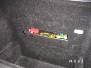
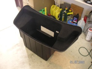
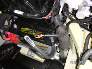
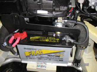
| Fig 2. Location of battery in Gallardo | Fig 3. Trunk "box" removed. | |
 |
 |
|
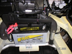
| Fig 4. Battery before switch | Fig 5. Battery with disconnect switch. | |
 |
 |
|
| Fig 6. Re-installing trunk rubber seal. |
Fig 7.
Rotary switch installed over battery.
|
|
 |
 |
|
| Fig 8. Connecting ground wire |
Fig 9. Ground wire battery connector
removed
|
|
 |
 |
|
| Fig 10. Both leads attached ready for switch |
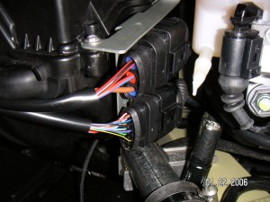
Fig 11.
Bracket that needs to be trimmed
|
|
 |
 |
|
| Fig 12. Bracket before trimming |
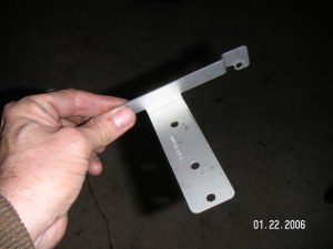
Fig 13. Bracket after trimming
|
|
 |
||
| Fig 14. Finished Switch |