 |

|
|
|
|
||
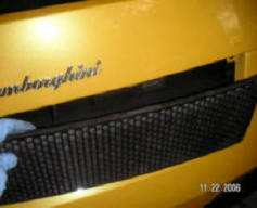
Installing a 2006 Lamborghini Gallardo OEM Muffler in a '05 (or earlier) Gallardo
The Lamborghini Gallardo has evolved in design and performance over the years. The '05 cars for example have the e-gear clutch system finally straightened out. They have a hydraulic front lifting system to raise the car 4'' when driving at low speeds in parking lots and over bumps on the road. Both are changes that in my opinion should have been there in the first place when the car came out in 2003.
One change Lamborghini made in the '06 and later cars was a re-design of the muffler (exhaust) system. The original '03-'05 was a little too tame/quiet for many users. Some upgraded their mufflers to Quicksilver, Larini, Tubi, Kreisseig or other custom mufflers. There seems to be almost universal agreement that the new Lamborghini designed muffler of the '06 and later Gallardo's are almost perfect. The sound is much richer and really sounds great at high engine RPM's.
 |
 |
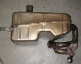 |
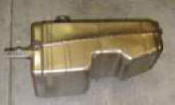
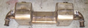
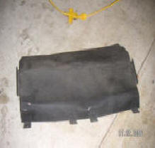
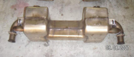
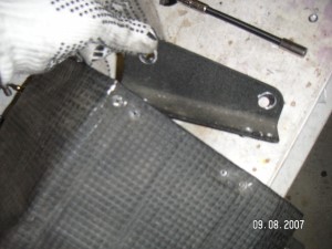
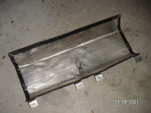
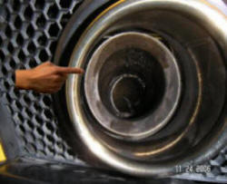
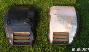
| Fig 1. Old (bottom) and new (top) Gallardo OEM Mufflers | Fig 2. Valve bypass in '06 Muffler | Fig 3. Valve bypass in '03-'05 Muffler |
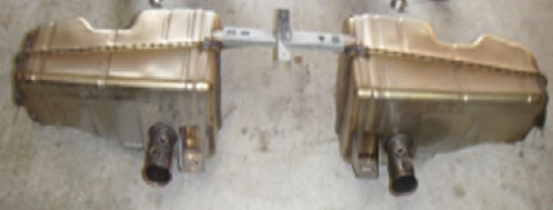
The reason for this are two major changes made to the muffler design. First as seen in Figure 1, in the '06 muffler the exhausts from the left and right cylinders now cross talk and share a common muffler box. In the earlier cars the had large separate boxes. This not only reduces the back pressures for each cylinder during the exhaust cycle (two outlets instead of one) but the sound is much better. Second when the engine RPM go above about 3000 RPM a valve opens and the exhaust gasses go straight out the tailpipe completely bypassing the muffler box entirely. This can be seen in figure 2. At low RPM's the exhaust comes in on the left hand side of the picture. In the middle it is diverted upwards into the box and comes out the tubes at the back. At high RPM's, the valve opens allowing the gas to flow freely through the "S" shaped tube. The same valves exist in the earlier cars, but in this case the exhaust always went through the muffler box. At high PPM's the opened valve system just allowed the exhaust to flow out (faster) through 2 tubes from the box instead of one narrow one (see, fig 3). So in the '05 and later Gallardo's there is essentially no muffler above 3000 RPM. A loud sound and -- according to some people -- a 10-20HP boost over that in the earlier cars.
I never did like the sound of the OEM muffler in my '05. I describe elsewhere on this site my experiences in installing a Quicksilver muffler. See here. I have used the Quicksilver muffler now for almost a year with good satisfaction. However upon hearing a friends Gallardo OEM '06 muffler I realized it was better. The OEM '06 muffler just simply seemed to give a more solid sound.
Now it turns out a number of people are changing out even their '06 mufflers for custom mufflers. This has yielded some cheap used '06 OEM mufflers on the used car parts market. I managed to pick up an essentially new used '06 Gallardo OEM muffler on eBay for an embarrassingly low number. Lets just say the shipping cost was higher than the purchase price! Could I install an '06 OEM muffler in a '05 Gallardo? At that price it was worth the experiment. To cut a long story short, the answer is yes, but it is not as simple as you might think. The problem is the supports for the '06 muffler in a '06 Gallardo are different than that from the earlier cars. After some experimenting I found a way to accomplish this. Furthermore no alteration to the frame etc. of the '05 car are made in case you wish to go back later to your old system. Let me describe the process in detail now
Removing the Current Muffler System
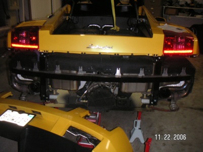
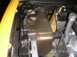
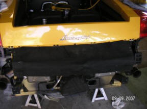
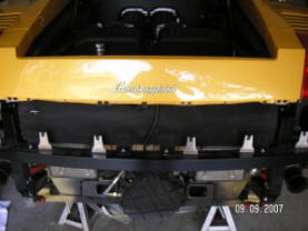
OK lets get started. First we have to remove the cover over the rear part of the engine. This is done by removing the screws around the edge of the cover (figure 4). Don't forget the one screw at the front between the two air filter housings. Also take care to store the screws in one pile. We will have many similar looking screws in this process. It's easy to confuse what screw goes where in the reassembly process if they are all in one pile. A little bit of care starting off can save much trial and error later! Figure 5 shows the car with the cover removed. The OEM mufflers can now be clearly seen.
 |
 |
 |
 |
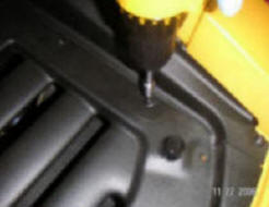
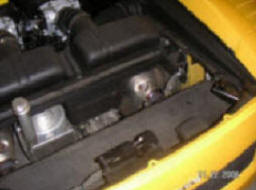
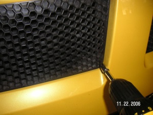
| Fig 4. Remove engine cover screws | Fig 5. Engine cover removed | Fig 6. Remove honeycomb panel screws. Fig 7. Remove panel. | |
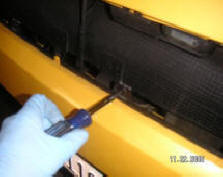
Next we will proceed to remove the five honeycomb panels at the rear of the car. If you carefully look at these you will see that there are small screws holding them in place. These screws take an "Allen wrench" to open. They have longer than you might expect treads. I use a power-tool to speed up the process. Figures 6,7 shows steps in this process. The good news is that all the screws are the same size. Remember each has a washer that can easily be left behind and lost.
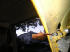
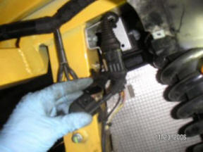
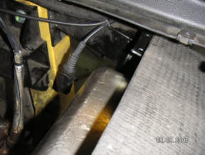
Next we need to disconnect the wire that is connected to the lights for the rear license plate. The wire is held to the rear frame with a clip as shown in Figure 8. This clip pulls away from the frame. Further up along the wire (under the right brake lights assembly) you will find a socket that allows you to disconnect the cable. In my case I also had wires connected to the rear radar detector and rear view camera. If you have not already done so you should have these connected via a socket as well as many times in the future you will have to remove the rear bumper of the car. Also as shown in Figure 9, one of the two larger screws need to be removed -- one on each side.
 |
 |
 |
 |
| Fig 8. Remove engine cover screws | Fig 9. Screws attaching bumper | Fig 10. Remove wheel well cover | Fig 11. Wheel well cover removed. |
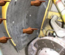
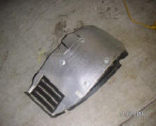
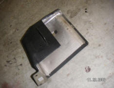
Now we need to remove both rear wheels and the back part of the wheel well covers. These are held in place by a number of screws. They are of 3 different sizes so make a note of which one goes where for re-assembly. At the top you will see 4 screws across. There are more along the side attaching the wheel well cover to the outside of the car. Some (but not all) are indicted in figure 10. At the very bottom (facing the ground) there are also two further screws with washers. Do NOT remove the 6 aluminum screws in the center of each panel. These are used to hold a heat insulation layer on the inside of the panel as seen in Figure 11.
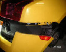
Now we are at the final stages of removing the rear bumper. First go along the back removing the 6+4 screws as shown in Figure 11. There are 4 large screws underneath the bumper (the black portion that joins it to the frame). Finally remove the larger bolt as shown in Figure 13 that is on the side now seen with the wheel well panel removed. After carefully removing all these screws the whole bumper pulls away from the car. Pull out the sides first as shown in figure 14. It is quite tight. Pull the front portion directly outwards. Then work your way around the back. The whole bumper is quite flexible. With care it is really not possible to brake anything. After you pull the side of the bumper out you will need to pull out the side indicator light. It easily pops out. Figure 14 shows the car with the rear bumper removed. All that remains is the strong aluminum "H" frame to which it was attached.
 |
 |
 |
 |
| Fig 12. Remove screws holding bumper to frame | Fig 13. Remove nut inside wheel well | Fig 14. Bumper partially removed | Fig 15. Bumper removed |
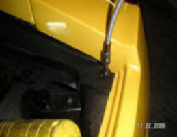
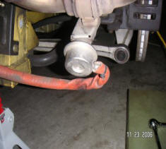
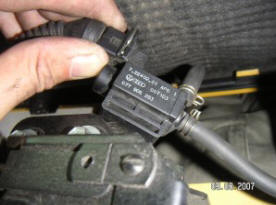
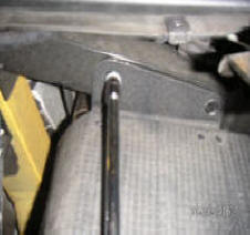
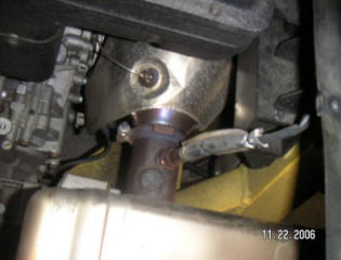
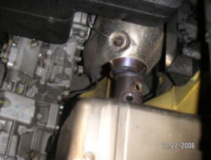
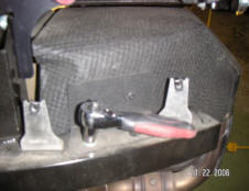
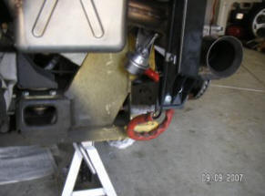
Next we remove the Aluminum "H" frame that supported the bumper. Unfortunately I don't have a photograph of this. It is attached to the rear frame of the car with 8 large bolts and 4 small bolts under the lights. Before removing it, you will see that attached to it is the vacuum tube that controls the muffler valves described above. This tube needs to be disconnected from each muffler valve (fig 16) and the electric vacuum control switch found under the hood latch (fig 17). We next need to remove the heat shield over the muffler in the center of the car. Again remove the necessary bolts (fig 18). This heat shield is quite flexible and can be slid out the back over the mufflers themselves (fig 19). It can be flattened out later to look nice before being reinstalled.
 |
 |
 |
 |
| Fig 16. Remove vacuum line connection to muffler | Fig 17. Disconnect tube to switch | Fig 18. Remove heat shield. | Fig 19. heat shield over muffler box removed |
We will now proceed to actually remove the OEM mufflers.
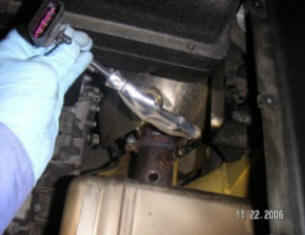
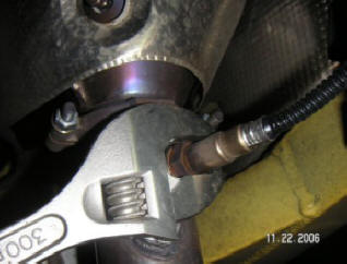
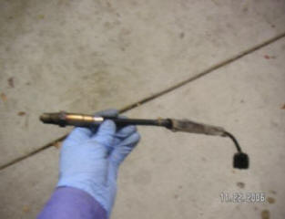
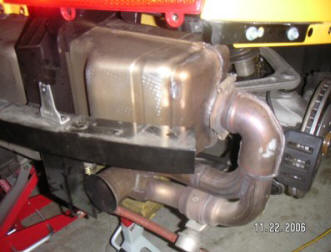
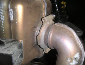
The OEM exhaust is shown in Figure 20. We can see in Figure 21 where the O2 sensor and exhaust access plug are situated. To remove the O2 sensor first we disconnect the wire lead from its socket in the wheel well area, Figure 22. There are 3 sockets in this area so be sure to disconnect the right one first. Now pull the O2 sensor wire through the frame and into the engine area Figure 23. Then carefully open the O2 sensor as shown in figure 24. In my car it was not real tight. I would avoid putting things like "liquid wrench" on the treads as I have heard they upset the O2 sensor when the car is restarted. Figure 25 shows the removed 02 sensor. Carefully store it away from oil rags etc.
 |
 |
 |
 |
| Fig 20. Lamborghini Muffler | Fig 21. O2 Sensor | Fig 22. Disconnect O2 sensor connection | Fig 23. Bring wires inside engine area |
 |
 |
 |
 |
| Fig 24. Remove O2 sensor | Fig 25. O2 Sensor removed | Fig 26. Muffler "C" Clamp | Fig 27. Muffler clamp removed. |
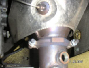
Now we need to remove the C clamp that connects the OEM muffler tube to the catalytic converter. This C clamp is shown in figure 24. I unfortunately used a air powered wrench to open the screws and broke one of the bolts. I put "Liquid Wrench" on the left hand side, let it sit for 20 minutes and it opened with no problem. Figure 26 shows the C clamp removed.
OK now we need to get to the exhaust tubes coming out of the OEM muffler. Part of each muffler in the wheel well area is surrounded by a heat shield box. This box (one each side) is attached via two bolts under the brake lights area. These are difficult to get at. There are also a two screws attached to the frame as shown in figure 28. Figure 29 shows the box removed. Figure 30 shows the exposed '05 OEM muffler. Remove the "C" clamp holding the exhaust tube with the valve (fig 31). The whole assembly then falls away, leaving only the OEM main muffler box.
 |
 |
 |
 |
| Fig 28. Remove side heat shield | Fig 29. Side heat shield removed | Fig 30. Exposed OEM Muffler | Fig 31. Remove "C" clamp attaching exhaust valve |
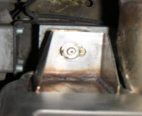
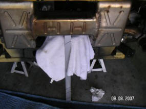
With both side exhaust tubes removed the muffler boxes themselves can them be removed from the car. Each box is attached via two bolts. One is shown in Figure 32. These supports contain a spring that allows the engine and muffler to shake/vibrate without affecting the rest of the car. The nuts tend to be tight! The whole OEM muffler lifts out as two pieces (fig 33). Be careful it is far heavier than you might think!
 |
 |
| Fig 32. One of two muffler supports for each muffler | Fig 33. '05 OEM muffler removed from '05 Gallardo |
Installing the '06 Muffler in the '05 Gallardo
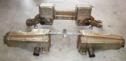
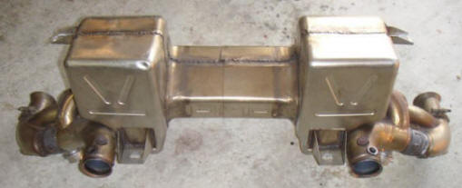
We are now ready to install the '06 muffler. Let us look closely at it. Figure 34 & 35 shows an enlarged picture of this muffler. The main issue we have is that of the 4 attachment points that hold the muffler in place only the two front points are in the same position as for the earlier '03-'05 muffler. The '06 muffler has the other two attachment points at the top of the muffler box.
 |
 |
|
| Fig 34. '06 OEM muffler (front view) | Fig 35. '06 OEM muffler (rear view) |
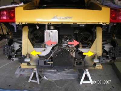
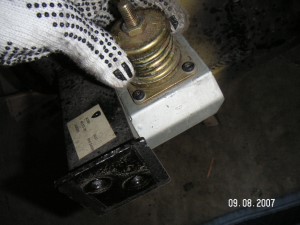
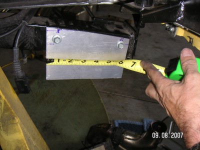
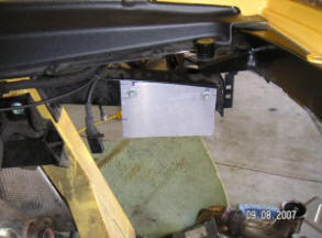
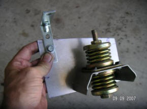
The muffler attachment points present in '03 to '05 Gallardo's is shown in figure 36 below. We clearly need to do something about repositioning the rear attachment points (yellow arrows) for our new '05 muffler. In the case of '03 - '05 mufflers they are low down near the bottom of the car. In the case of the '06 muffler they are above the muffler box. First we remove the lower attachment point spring support unit. It is attached to the frame with two small bolts (fig 37). We are now going to attach it to the corresponding top frame piece of the car. To do this I cut out a piece of 1/8'' aluminum and bolted it to the frame as shown in figures 38,39. The reason this piece is so large is that it utilizes the same holes and bolts as the '05 heat shield used (see figure 18 above). This way no new holes are drilled into the frame of the car.
 |
 |
 |
| Fig 36. Attachment points for '05 muffler | Fig 37. Bottom attachment spring | Fig 38. New support bracket. |
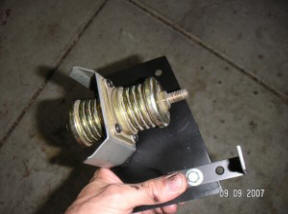
Next we add the spring assembly to this piece of aluminum as show in figure 40. Note there is also a right angel bracket that is held in place via one of the bolts when it is attached to the frame of the car as well. in the photograph it is just held in place with my finger. This bracket is to retain the top of the heat shield as we will see later. The whole thing is sprayed black (fig 41) when done. To be on the safe side I used high temperature engine black paint. Probably over kill but it does get hot around there.
 |
 |
 |
 |
| Fig 39. New support bracket. | Fig 40. Bracket with spring. | Fig 41. Spray bracket black. | Fig 42. New muffler held in place |
Two of these brackets are made. Now fortunately if you use the approach I described above and place the brackets exactly as I described the spacing apart between the two posts exactly fits the top two attachment points of the '06 muffler. No alteration to the car or '06 muffler is required!
Next we lift the '06 muffler into the car. Be real careful it is heavier than it looks. Be careful not to damage the tubes and wires going to the transmission box below. You will find that it nicely sits on the two bottom attachment points and can be simply held in place with a bar as shown in figure 42. Fig 42a below shows the position of the two new supports.
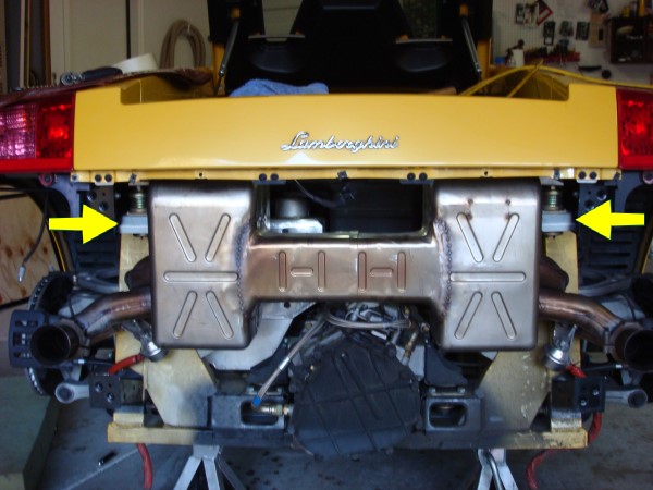 |
| Fig 42a. Arrows point to the two new relocated supports. |
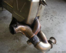
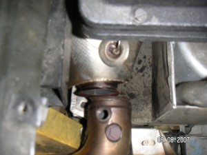
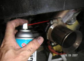
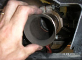
The next complication I had was that the inlet to the new muffler did not exactly line up with the outlet from the cats on the engine side. See figure 43. Fortunately at the front of each cat is a "C" clamp (figs 44, 45) that can be opened allowing the cats themselves to be moved around. The cat on the right side of the car was easy both bolts on the "C" clamp could be opened. On the left side I could only get to one bolt. The other would involve major work getting to it. Fortunately loosening one bolt was enough to reposition the cat outlet. Use "loose nut" spray, and leave for 10 minutes to loosen these nuts beforehand. You don't want to brake them! Do not tighten the cats back up yet. Now attach the "C" clamps described in figure 26 to the new muffler and cat outlet. Juggle the muffler box around so things fit without strain. Do not tighten the "C" clamp bolts yet. Then bolt in the muffler to the 4 attachment points. Again juggle the box around so it fits comfortably. Do not tighten the 4 bolts down completely yet.
 |
 |
 |
| Fig 43. Alignment problem | Fig 44. Cats position adjustment. | Fig 45. Loosen Cat "C" clamp bolt |
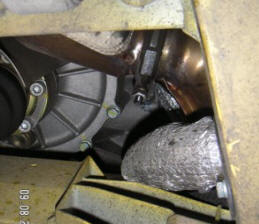
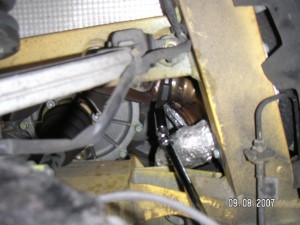
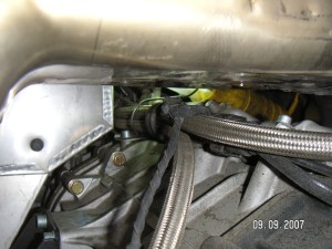
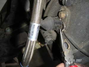
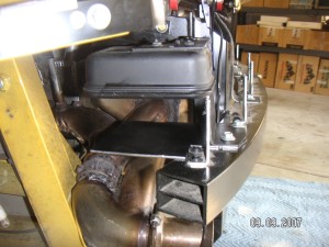
One thing that is different about this new arrangement is the muffler runs close to the cables and tubes going to the transmission. As shown in figure 46 some of the wires are only an inch away. Now while most of the heat is absorbed by the box insulation, I felt uneasy about the close distance. I found that you can disconnect the connector (fig 47) and re-route the wires below the steel braded tubing. As shown now in figure 48 there is much more distance.
 |
 |
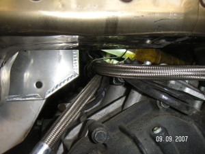 |
| Fig 46. Wires close to muffler problem | Fig 47. Open socket | Fig 48. Relocate wires lower down |
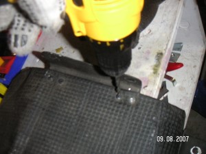
Next we need to slide the muffler heat shield (shown in figure 18,19) back over the new muffler. The only complication we have is that the new muffler is about 2'' higher than the old '05 muffler. Fortunately this heat shield is very flexible. However we do have to remove the original top support brackets (fig 18). These no longer fit to the frame. They are held in place by "pop gun" studs and can be easily removed by drilling the top of them (fig 49). Store the brackets in case you want to go back to the old muffler later.
 |
 |
 |
| Fig 49. Remove heat shield bracket | Fig 50. Remove heat shield bracket | Fig 51. Heat shield ready to install |
Flatten the heat shield out evenly on the ground. Then fold it as shown in figure 51. You then slide it over the muffler box and under the top frame part of the car as shown in figure 52. Slide it over the bracket described in figure 40,41 and shown in figure 53. Then install the Aluminium "H" frame. It takes 8 large bolts and 2+2 smaller bolts under the lights. Attach the above heat shield to this frame as shown in figure 54. Next re-attach the O2 sensors (fig 55). Hook up the wire connector as it was under each wheel.
 |
 |
 |
|
| Fig 52. Slide in rear heat shield | Fig 53. Side heat shield over support | Fig 54. Rear heat shield installed | Fig 55. Re-attach the O2 sensors |
Now we need to connect the vacuum tubing to each of the control valves. The tubing slides on nicely. You do not need new hose clamps. Make sure to pull the heat insulation up over the end of the rubber. See figure 56.
Because the exhaust tubes of the new muffler do not branch out behind the wheels (and are insulated) we really don't need the side heat covers that came with the earlier cars. These side covers (fig 29) can be stored if you want to put them back in the car. If you put them in now they are just extra weight. It's your choice. You will have much better rear end cooling through the rear vents without these shields.
Next we need to adjust the short outlet tips of the muffler so they line up exactly with the chrome tips in the bumper. Add "loose nut" spray to free up the bolts (fig 57), loosen them. Then by hand check they can be moved around (fig 58). Install the rear bumper and all the bolts you saved during its removal. Jiggle the muffler box, cats and exhaust tips so they all fit comfortably. Make sure the tips are free from the chrome port s in the bumper. Tighten all nuts.
 |
 |
 |
 |
| Fig 56. Reconnect vacuum line hose | Fig 57. Free-up bolts | Fig 58. Check this can move around | Fig 59. Make sure tips are not touching |
Next we add back the wheel well covers. Now if you had chosen not to install the side heat shields you will see that the silver insulation on the inside of these covers is visable at a certain angle through the honeycomb grill at the back of the car. I painted mine black (fig 60). This way the inside appears black when you are done. The next time I am in there I will paint the rear frame black as well. You can just make out its yellow color.
 |
 |
 |
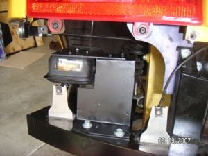
| Fig 56. Spray heat shields black | Fig 57. Repositioned rear radar detector | Fig 58. Side view or radar detector |
One of the reasons I did not want to install the side heat shields is that in my car I had a rear facing radar detector pointing through the grill in the mid section. This is all described in detail elsewhere on this site. Since the new muffler is higher it would not fit in that position. I relocated the detector to one of the empty wheel well areas making a new support. See figures 58 and 59. Note the black metal disk below the radar unit in fig 58. This is to deflect heat away from the radar electronics.
Everything else was put back without incident. I have driven the car hard so far for 50 miles with no problem with OBDII lights etc. Delighted with the change!
How does it sound.
It is difficult to describe sound differences for mufflers on cars. As with music, it tends to be a very personal thing. I have here two files that give the sound of the '05 OEM and OEM '06 mufflers in above car. Let me quickly say the sound from these files do not do either type of muffler justice. I recorded the sound in a small confined garage with a simple video camera. I cannot explain the grinding noise (particularly for the OEM muffler). I think the microphone is sensitive to different frequencies than that of the human ear.