 |

|
|
|
|
||
Lamborghini Shock Absorber Error Codes
|
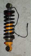
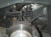
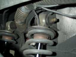
There are six heavy duty shock absorbers under a two
ton Lamborghini Diablo. One for each front wheel and two for each rear wheel. This weight puts considerable strain on the six
KONI shock absorbers of the
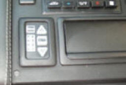
car. The softness of these absorbers can be adjusted by the driver by means
of "up/down" buttons in a ride control unit located in front of the
gear shift leaver of the car. There are 4 possible settings. One being soft, four
very stiff, making the car behave almost as if there are no shocks present at
all.
There is also an "auto" setting which allows the cars computer to
match the settings with road conditions and speed. If any of the
shocks fail to respond to the onboard computer in the car a red error light will
blink in the ride control unit. What can be the problem?
|
|||||||||||||||||||||||||||||
|
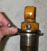
Well for one thing in the post 1994 models, the
front of the car can be raised about 4 inches when traveling at low speed by
means of a manual switch operated by the driver. This is extremely useful in
parking lots and over rough road surfaces. Consequently the front two shock
absorbers on these cars is more elaborate in that they are hydraulically
controlled (See figure 6). With extended usage they can leak
a little oil. This will not only generate an error but lock the unit into a
setting 3 stiffness for all road conditions. Other
shock absorber failures can also occur. How can we determine which
absorber is at fault? Do we have a faulty electrical connection to a
shock, or is there something wrong with the shock itself? Fortunately Lamborghini has installed in the car a
computer driven series of tests to locate which wheel affected and help
diagnose the problem.
|
||||||||||||||||||||||||||||||
First Test Level.
|
||||||||||||||||||||||||||||||
|
If
an error appears for the front wheels things are a little simpler than
for error codes for the rear wheels. In the case of the rear
wheels because there are two shocks per wheel it will be unclear which
of the two shocks are at fault. Perhaps even both have failed.
If there are no problems with all the shocks the error light will come back on and flash rapidly and continuously at 5Hz.
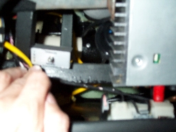
Second Test Level. This brings us to the second phase of diagnostic testing. This is used if a faulty shock is indicated in the above test. It checks if the problem is related to one or more of the actual shocks or is due to some other part of the suspension control system. Start the test by first pressing the "Auto" button. Again the error light will flash at 0.6Hz. Disconnect the electrical connection going to the shock absorber. It is a 3 pin socket (see figure 6). Obtain a simple voltmeter. Press the "Auto" button one more time. Measure the voltage between pin 2 and 3 of the connection from the car to the shock absorber. It should be between 0.7 to 1.3 volts. The voltage between pin 1 and 3should be between 10 to 15 volts. If these values are correct the system itself is OK and the failure is in the shock absorber(s) itself. Sometimes the shock is OK, its the electrical connection in the connector that is bad. A spray of TV tuner lubricant can quickly fix the problem!
Third Test Level. The third test of the suspension system is to make sure the speed sensor to the ride control system is working correctly. Again we press the "Auto" button. The error light will flash again at 0.6Hz. Press the auto button again. At this point the error light will stay on. Drive the car at increasing speed. The light should start flashing at about 20 MPH. If it stays permanently on, there may be a connection problem with the speed indicator in the car. This will lock the suspension into a (stiff) 3 setting mode. After all tests are completed remember to reset the computer switch under the passenger side dashboard. Switch off the ignition switch, this will reset the computer controlled shock absorber to its normal functional mode. |
||||||||||||||||||||||||||||||