 |

|
|
|
|
||
Removing the Engine From a Diablo
|
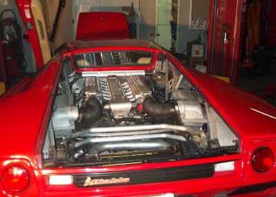
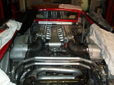
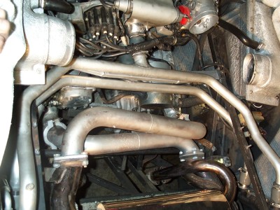
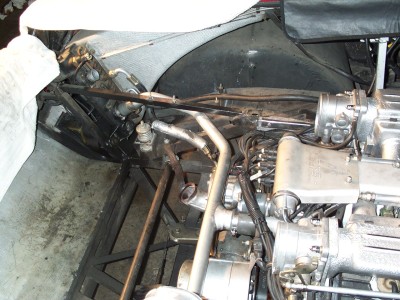
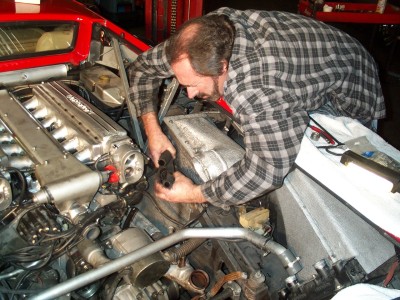
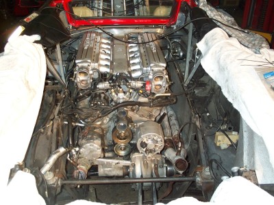
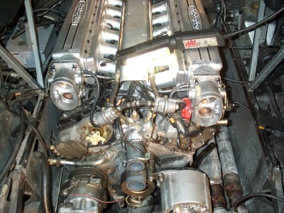
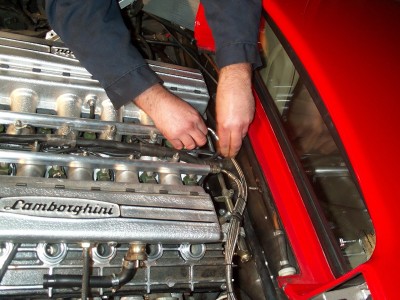
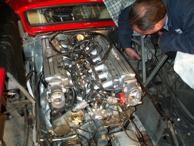
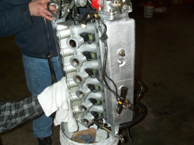
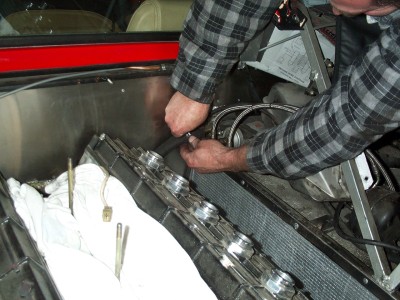
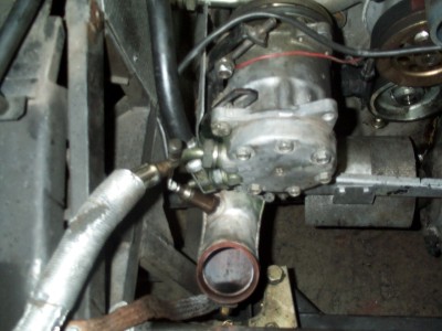
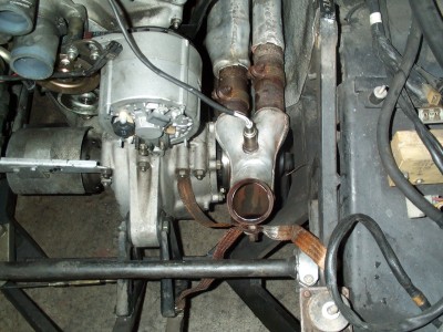
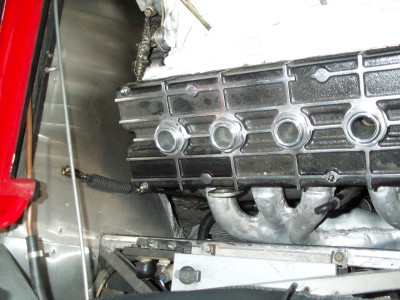
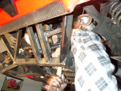
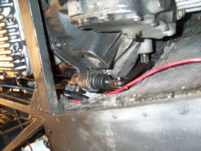
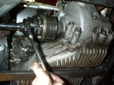
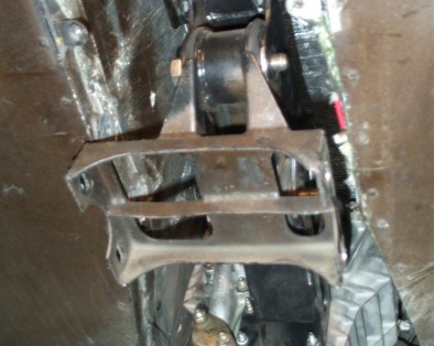
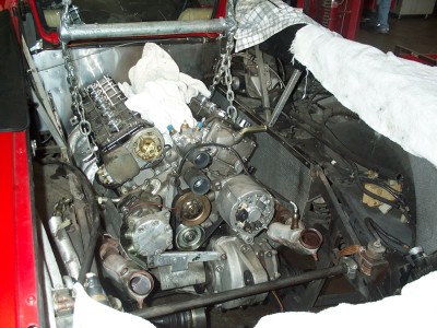
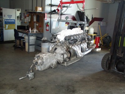
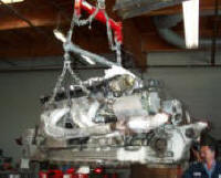
OK lets get started. We are going to work here on a 1992 Diablo. This is a car owned by Dave Ayers in Sacramento CA. The process is essentially the same for all Diablo's - even the 6.0L version. First we remove and set aside the engine cover and back cover including the spoiler. This gives clear access to the engine and exhaust system. See Fig. 2 below. In order not to scratch the paint it is essential to surround the whole area of the car with a cloth cover. Do not think for one moment you will remove the engine without scratching the car without such a cover. Next we disconnect the battery. Then remove the air ducts connecting the air intake to the engine. The muffler is removed by opening bolts near ground level and C clamps attaching it to engine (Fig 3). Fig 4 shows the muffler completely removed. Next we need to disconnect the water hoses to the engine (Fig 5). This can be a real messy job. Remember to first drain both radiators of all fluid . Next you need to remove the two Y shaped aluminum tunes that connect the water radiators to the car. They are connected with hose clamps and silicon rubber tubing. Note how tight they are. You will need to remember this when re-connecting them later. Figure 6 shows the car with all water hoses removed. Next we remove the distributor cap, spark plug wires and the wires connecting the distributor to the ignition coils under the left fender. On later model cars the arrangement is slightly different since each plug has its own coil. In any event the rotor cap and wires have to be removed. Fig 7 shows the engine with this part removed. Be careful of the naked white plastic rotor arm it is now exposed when handling the engine. Next we remove the fuel lines to the engine. These come directly from the gas tank through the fuel pump up to the front of the fuel line rail. Figure 8 shows these being opened. Next all electrical connections from the engine to the rest of the car are disconnected. These are primarily connections to the cars LIE computer system. Be extremely careful to color code and note which connection goes where.. While some connectors are different from each other there are a few that can me cross mixed. In order to get to some of these connectors you have to displace the water overflow tank and air filter boxes Fig 9. Next we remove the head manifold cover Fig 10. This is necessary because the attachment points for the chains to lift the engine out of the car will press on this cover and scratch/dent it. It is held in place with three bolts along the center of the engine. Be sure and cover the exposed engine piston air inlets with a cover immediately after removing the manifold cover. You do not want to have anything fall into that place. This is shown in Fig 11. Next we have to disconnect the air conditioning hoses. You need to first drain the system of air conditioning fluid. This requires a specialized piece of equipment. You may rent it or get it done at an A/C shop before you start this work. Then open the connection to the compressor (Fig 12). Thinking about this in retrospect It may be possible to disconnect the compressor and leave it hanging free of the engine without disconnecting hoses. This would simplify things greatly. In any event if you do disconnect the A/C hoses be very careful to keep the ends clean. Any dirt in the system will cause compressor failure later. Next is an easy one. We disconnect the copper braded ground wires that attach the engine to the frame of the car. These ground wires are seen in figure 13. Next we disconnect the accelerator cable at the front of the engine Fig 14. Then we open the bolts attaching the rear of the engine to the frame of the car. The bracket attaches to the rear axel differential unit, Fig 15. Next we need to disconnect the oil line going to the clutch slave cylinder (Fig 16). Watch out for oil leaks! Next we disconnect the axle rod connections for the rear wheels, Fig 17. There are four bolts and two c shaped brackets involved. Note as you disassemble this part that there are two sprockets (one between each pair of bolts) that must be lined up for the unit to fit together. Next we release the front engine mount from the frame of the car. There are four bolts holding the support to the frame of the car and one large bolt attaching the engine itself to this support Fig 18. The gear shift leaver running into the interior of the car also needs to be disconnected. This involves removing the shift ball and shift gate. Opening the 4 bolts attaching the unit to the frame and dropping it down between the central well of the car. Now comes the exciting part. A hoist with four chains is attached to the engine as shown in figures 19 and 20. and the whole engine is carefully lifted out of the car. This will take some time a few inches at a time. Make sure nothing catches to the car frame. It is necessary to change the angle of the engine as it is being removed from horizontal to about 50 degrees. Two people holding the swinging engine can easily do this while another raises it mechanically. Figure 21 shows car with engine removed.
|
||
 |
 |
|
| Fig 1. Engine cover and rear spoiler removed | Fig 2. Covers are surrounded the engine to protect the paintwork. | |
 |
 |
|
| Fig 3. Remove muffler by opening bolts near ground level and C clamps attaching it to engine. | Fig 4. This picture shows the muffler removed from the car. Note the exhaust tube in the center of the picture. | |
 |
 |
|
| Fig 5 Water hose removal. One Y shaped radiator connection tube to radiator has been removed. | Fig 6. Water hoses removed from car. Note two connections to radiator hose in center of picture are now visible. | |
 |
 |
|
| Fig 7. Distributor cap and spark plug wires removed. | Fig 8. Fuel lines being opened and removed. | |
 |
 |
|
| Fig 9. All electrical connections from the car to the engine are carefully disconnected. | Fig 10. Head manifold cover removed from engine. | |
 |
 |
|
| Fig 11. Cover air inlets to prevent debris falling into cylinders. | Fig 12. Remove air conditioning fluid and disconnect tubing. | |
 |
 |
|
| Fig 13. Ground wires attached to frame of car. | Fig 14. Disconnect accelerator cable. | |
 |
 |
|
| Fig 15. Remove bolts to rear engine mount. | Fig 16 Clutch slave cylinder. Disconnect oil line. | |
 |
 |
|
| Fig 17. Disconnect rear wheel axels from engine. | Fig 18. Release front engine mount. | |
 |
 |
|
| Fig 19. Engine removal, start of process. | Fig 20. Engine removed from car. | |
|
|
|
|
| Fig 21. Car with engine removed. | Fig 22. Car with engine removed viewed from below. | |
 Removing the
engine from a Diablo is quite a complex task. There are a number of times
you may need to remove the engine from the car. The most common being when
you need to change the clutch. I will present at a later date information as
to how to do that . Right now lets concentrate on just getting the engine
out. You will need a few specialized tools and at least one other person to
help you. The engine itself weighs almost 1 ton, so a way to mechanically hoist
it out of the car is essential.
Removing the
engine from a Diablo is quite a complex task. There are a number of times
you may need to remove the engine from the car. The most common being when
you need to change the clutch. I will present at a later date information as
to how to do that . Right now lets concentrate on just getting the engine
out. You will need a few specialized tools and at least one other person to
help you. The engine itself weighs almost 1 ton, so a way to mechanically hoist
it out of the car is essential.